
Overview: This guide explains how to read a converter diagram: the parts inside the shell, where the unit sits in the exhaust, what happens to each gas, and how a diesel system is drawn differently. It is written for vehicle owners, workshops and scrap traders who want to understand what they are looking at, and where the value sits when a unit is recycled.
Key Takeaways
- A converter is a steel shell holding a ceramic or metal honeycomb whose thin channels are coated with a porous washcoat and small amounts of platinum, palladium and rhodium.
- On a gasoline car, exhaust flows from the engine through the exhaust manifold, an upstream oxygen sensor, the converter and a downstream oxygen sensor, then on to the muffler and tailpipe.
- A three-way unit treats three gases – carbon monoxide, hydrocarbons and nitrogen oxides – and today’s devices can convert as much as 98% of them into less harmful gases.
- The onboard diagnostics system compares the two oxygen sensors to judge the converter and turns on the check-engine light when performance drops too far.
- Diesel systems are drawn differently: an oxidation catalyst, a diesel particulate filter and a selective catalytic reduction unit fed with diesel exhaust fluid.
- The value of a used unit sits in the coated honeycomb, which holds roughly 1-2 grams of platinum group metals in a small car unit and 12-15 grams in a big truck unit.
A catalytic converter is a steel can in the exhaust pipe with a coated honeycomb inside that turns harmful exhaust gases into less harmful ones. A diagram of one is simpler than it looks: read it from left to right, following the gas from the engine to the tailpipe, and every label falls into place.
Every automotive catalytic converter follows the same basic layout, whether it comes from a small hatchback or a pickup truck. The size, the shape and the mix of metals change, but the order of the parts does not, so it is worth learning once. This guide walks through the three kinds of diagram you are most likely to see: a cut-away of the parts, a line diagram of the exhaust and a diagram of the chemistry.
What does a catalytic converter diagram show?
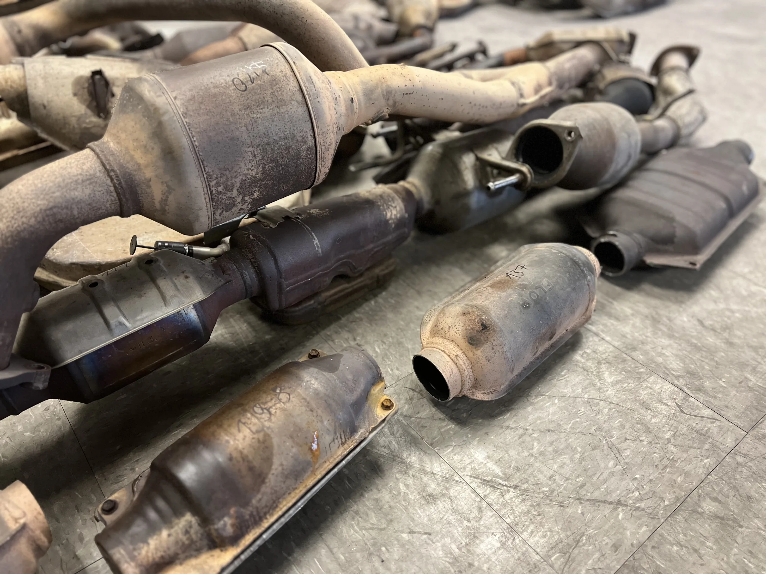
A catalytic converter diagram shows two things: the parts inside the unit and where the unit sits in the exhaust. Most combine a cut-away view of the shell with arrows that show the gas flowing through it. For background on the converter’s job and its environmental role, see our guide on how converters work and why they matter.
| Part | What it is | What it does |
|---|---|---|
| Heat shield | Thin metal cover around the shell | Protects nearby parts and the vehicle floor from heat |
| Steel shell | Metal housing with an inlet and an outlet | Holds the parts together and connects to the exhaust pipe |
| Insulating mat | Layer wrapped around the honeycomb | Holds the honeycomb in place and insulates it |
| Honeycomb (substrate) | Ceramic or metal block full of thin parallel channels | Gives the exhaust a very large surface to flow over |
| Washcoat | Porous layer of aluminum oxide on the channel walls | Increases the surface area further and carries the metals |
| Precious metals | Platinum, palladium and rhodium in the washcoat | Speed up the reactions that clean the exhaust |
| Oxygen sensors | Sensors before and after the converter | Help control the air-fuel ratio and check the converter |
Sources: Chemistry LibreTexts; California Air Resources Board OBD overview.
Catalytic converter simple diagram: the parts from the outside in
A catalytic converter simple diagram strips the unit down to five layers. In an automobile catalytic converter, they are, from the outside in:
- Heat shield – the outer cover that keeps heat away from the floor and nearby parts.
- Steel shell – the can itself, with an inlet pipe on one end and an outlet pipe on the other.
- Insulating mat – the layer that grips the honeycomb and stops it rattling or cracking.
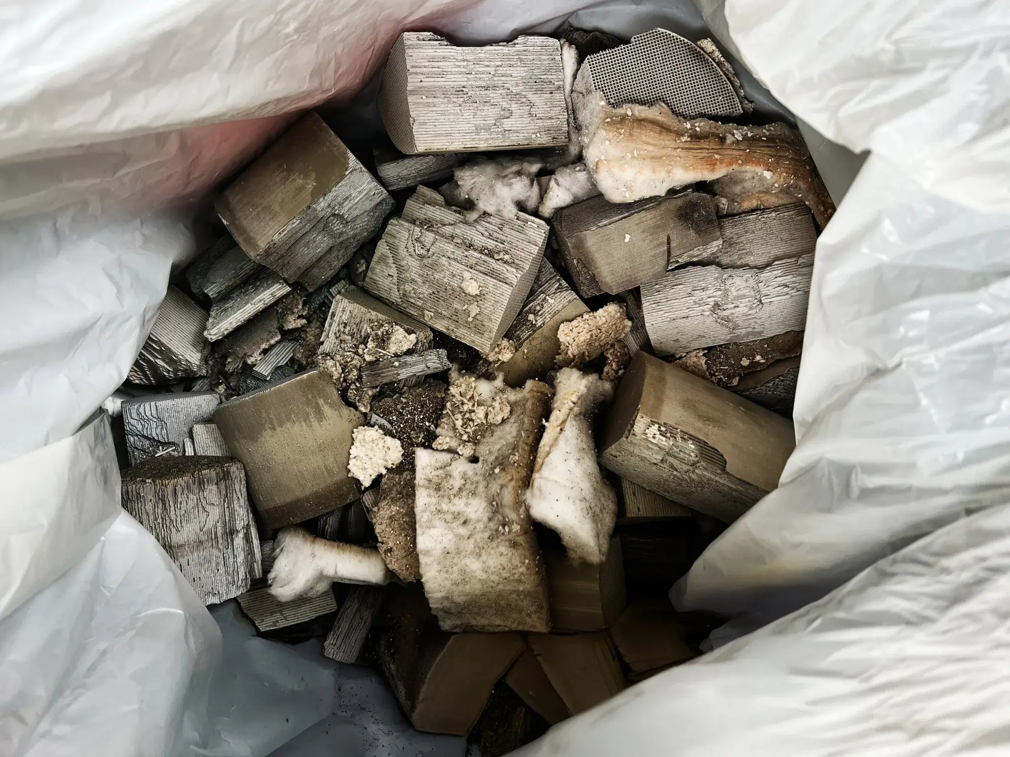
- Honeycomb – the ceramic or metal block with thousands of thin channels running from end to end.
- Washcoat and precious metals – the coating on the channel walls, where the chemistry happens.
The honeycomb is the part diagrams draw biggest, and for good reason. According to the Science History Institute, the honeycomb structure inside the metal casing vastly increased the surface area of the catalyst that comes into contact with the exhaust. Chemistry LibreTexts describes the next layer: the thin channel walls are coated with aluminum oxide, a porous washcoat that increases the surface area again, and the washcoat holds the platinum, rhodium and palladium.
Catalytic converter line diagram: from engine to tailpipe
A catalytic converter line diagram draws the exhaust as a single line with the converter as one box on it. On a typical gasoline car, it reads:
Engine → exhaust manifold → upstream oxygen sensor → catalytic converter → downstream oxygen sensor → muffler → tailpipe
Some vehicles have more than one converter, for example a small unit close to the engine and a larger one further along the pipe. On a line diagram, that simply shows up as two boxes.
Why are there two oxygen sensors?
The two sensors on either side of the converter do different jobs. The upstream sensor measures oxygen in the exhaust so the engine computer can keep the air-fuel ratio close to the stoichiometric point, the ratio at which a three-way converter works best. The onboard diagnostics (OBD) system then compares the readings before and after the converter. According to a California Air Resources Board OBD overview, the converter’s ability to store oxygen is used to infer how well it converts hydrocarbons, and once performance drops past the malfunction threshold, the system turns on the malfunction indicator light and stores a fault.
| Sensor | Position | Job |
|---|---|---|
| Upstream oxygen sensor | Between the exhaust manifold and the converter | Measures oxygen so the engine can keep the air-fuel ratio near the stoichiometric point |
| Downstream oxygen sensor | After the converter | Compared with the upstream sensor to judge how well the converter is working |
Sources: California Air Resources Board, OBD Program Overview (2015); Chemistry LibreTexts.
Catalytic converter working: what happens inside the honeycomb?
The catalytic converter working principle is two chemical jobs at once. Oxidation adds oxygen to carbon monoxide and hydrocarbons, and reduction removes oxygen from nitrogen oxides. The precious metals speed up both reactions without being used up. According to the Science History Institute, today’s three-way devices can convert as much as 98% of these three gases into their less harmful counterparts.
| Gas going in | Reaction | What comes out |
|---|---|---|
| Carbon monoxide (CO) | Oxidation: 2CO + O2 → 2CO2 | Carbon dioxide |
| Hydrocarbons (HC) | Oxidation: CxHy + (x + y/4)O2 → xCO2 + (y/2)H2O | Carbon dioxide and water |
| Nitrogen oxides (NOx) | Reduction, for example 2NO + 2CO → N2 + 2CO2 | Nitrogen |
Sources: Chemistry LibreTexts; Science History Institute.
Each metal has a main job. Platinum and palladium mainly drive oxidation, while rhodium handles nitrogen oxides: the Royal Society of Chemistry notes that about 80% of rhodium is used in car catalytic converters, where it reduces nitrogen oxides, and that converters account for about half of annual platinum demand.
The reactions also depend on the engine. Chemistry LibreTexts explains that a lean mixture, with more oxygen than needed, favors the oxidation of carbon monoxide and hydrocarbons, while a rich mixture favors the reduction of nitrogen oxides, which is why the engine computer keeps switching around the ideal point. The reactions also need heat, so a cold converter does little until it warms up.
Two-way and three-way units in a diagram
A two-way unit only oxidizes carbon monoxide and hydrocarbons, so its diagram shows two gases being treated and nitrogen oxides passing straight through. A three-way unit, the standard on modern gasoline cars, treats all three gases. If a diagram shows only oxidation arrows, it is describing an older two-way design or a diesel oxidation catalyst.
How is a diesel exhaust diagram different?
A diesel exhaust diagram usually shows several boxes instead of one. According to the U.S. Department of Energy’s Alternative Fuels Data Center, the exhaust passes through a diesel particulate filter (DPF) and a diesel oxidation catalyst to reduce particulate matter; diesel exhaust fluid is then added, and the mixture is treated in a selective catalytic reduction (SCR) unit, which reduces nitrogen oxides to nitrogen and water.
On a line diagram, that becomes: engine, oxidation catalyst, particulate filter, diesel exhaust fluid injector, SCR unit and tailpipe. The filter traps soot rather than converting gases, which is why it is easy to confuse with a converter. Our guide explains how a DPF differs from a converter and how to tell the two apart before you sell either one.
Which parts of the exhaust line are worth recycling?
Engine → manifold → oxygen sensor → catalytic converter → oxygen sensor → muffler → tailpipe
The coated honeycomb inside holds platinum, palladium and rhodium.
Engine → manifold → oxidation catalyst → particulate filter → fluid injector → SCR unit → muffler → tailpipe
Coated with precious metals to treat carbon monoxide and hydrocarbons.
Some filters are coated with precious metals and some are not, and SCR catalysts are commonly vanadium-based. Send the part number first.
Where is the value in a catalytic converter diagram?
On a recycler’s diagram, almost all the value sits in one layer: the washcoat on the honeycomb. That is why refiners and recyclers often call the whole unit an auto catalyst – the catalyst coating is the part that matters. Thermo Fisher Scientific notes that most recycled converters in the US contain recoverable platinum group metals ranging from 1-2 grams for a small car to 12-15 grams for a big truck.
When a unit is recycled, the shell is cut open, the coated honeycomb is removed and ground into a uniform sample, and the sample is assayed to measure how much platinum, palladium and rhodium it contains. That is also why condition matters: a dented or rusty shell is fine, but a honeycomb that is broken, melted or emptied has lost some or all of its recoverable metal. Keep units intact and let the buyer grade them by their code.
Conclusion
Once you know the order of the parts, every catalytic converter diagram tells the same story: gas leaves the engine, passes an oxygen sensor, flows through a coated honeycomb where precious metals clean it, passes a second sensor and leaves through the tailpipe. Diesel diagrams add a filter and an SCR unit, but the logic is the same.
The same diagram also shows where the value is when a unit reaches the end of its life. If you have used converters to sell, contact the Recohub team for an assay-based quote.
FAQ
What does a catalytic converter diagram show?
It shows the parts inside the unit – a steel shell, an insulating mat, a ceramic or metal honeycomb, and a washcoat holding platinum, palladium and rhodium – and where the unit sits in the exhaust, between the exhaust manifold and the muffler, with an oxygen sensor on each side.
What is inside a catalytic converter?
A honeycomb block full of thin channels, held in a steel shell by an insulating mat. The channel walls are coated with a porous washcoat of aluminum oxide that carries small amounts of platinum, palladium and rhodium, the metals that drive the chemical reactions.
Why are there two oxygen sensors around a catalytic converter?
The upstream sensor helps the engine computer keep the air-fuel ratio near the ideal point. The onboard diagnostics system compares it with the downstream sensor to judge how well the converter is working, and turns on the check-engine light if performance drops too far.
How does a catalytic converter work?
Exhaust gas flows through the coated honeycomb, where the precious metals speed up two kinds of reaction. Oxidation turns carbon monoxide and hydrocarbons into carbon dioxide and water, and reduction turns nitrogen oxides into nitrogen. Today’s three-way units can convert as much as 98% of these gases.
Is a diesel exhaust diagram different?
Yes. A diesel system usually shows several units instead of one: a diesel oxidation catalyst, a diesel particulate filter that traps soot, and a selective catalytic reduction unit that uses diesel exhaust fluid to turn nitrogen oxides into nitrogen and water.
Which part of a catalytic converter is valuable?
The coated honeycomb. The precious metals sit in the washcoat on its channel walls, so a unit with a broken, melted or emptied core has lost some or all of its recoverable value. Keep units intact when you sell them.